On-site hydraulic servicing, engineering & spare parts sales


Hydraulic faults are often misdiagnosed because a normal gauge reading is treated as proof that the circuit is working correctly. Pressure can still be lost across valves, hoses, filters or return lines, while inadequate flow and transient pressure spikes can also remain undetected. Identifying the source of the problem requires targeted measurements that show how pressure changes across the circuit under load.
This article delves into the limitations of single-point assessment and the additional information needed to identify pressure losses, blocked flow paths and control faults.
A pressure value describes conditions only at the selected connection. It does not show how pressure changes throughout the circuit.
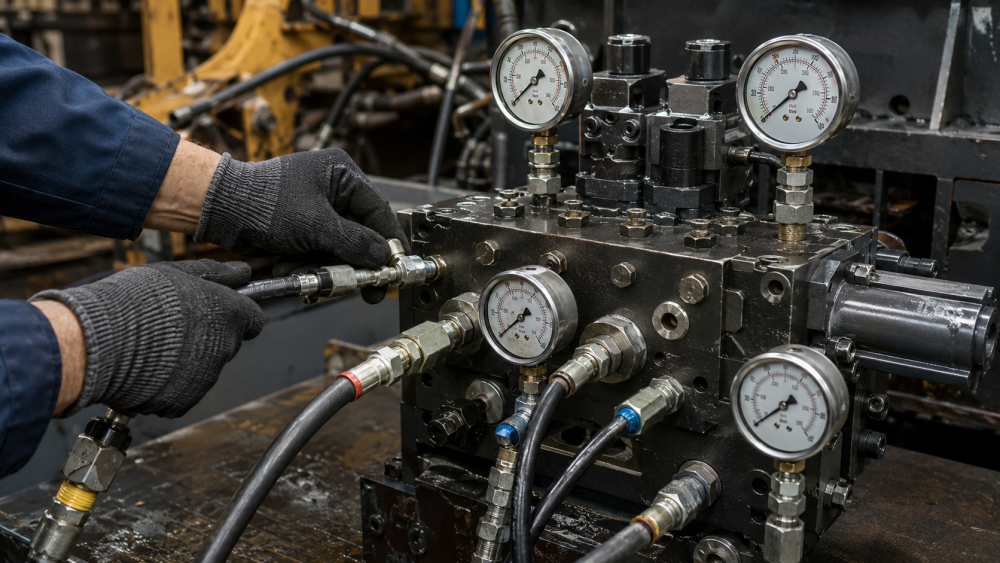
Consider a system in which the pump outlet reaches the specified pressure, but the cylinder moves slowly and produces insufficient force. The outlet value can appear correct while an obstruction in the flow path reduces the pressure reaching the cylinder, which becomes apparent when a second gauge is installed at the cylinder port.
Potential causes include:
The opposite can also occur. Low pump pressure can result from internal bypass through a control valve or cylinder, or from oil being diverted through a pressure-control device. Replacing the pump based solely on its outlet value would not correct the underlying fault.
Test points should instead be selected to isolate specific sections of the circuit rather than chosen only because they are easy to access.
Pressure and flow describe different aspects of hydraulic behaviour. Pressure reflects resistance, while flow determines actuator speed and the rate of hydraulic energy transfer.
A system can reach full pressure while delivering inadequate flow. A worn pump can pressurise a closed or low-flow circuit but fail to maintain the required output once the actuator begins moving.
The resulting symptoms include:
When investigating pump output, actuator speed or internal leakage, pressure data should be supported by flow measurement.
A flow meter establishes whether the pump is delivering the specified volume and how its output changes as pressure and oil temperature increase.
Pressure drop is established by comparing values immediately before and after a device while oil is flowing. A value from one side alone cannot establish the loss across that device.
For example, a return filter might show 8 bar at its inlet. That value appears excessive, but if downstream pressure is already 6 bar, the actual pressure drop across the filter is only 2 bar.
This method can be used to assess:
An excessive pressure drop across any device indicates an obstruction that can reduce available force or torque, slow movement, and generate heat.
Supply pressure alone does not determine the force available at the cylinder. Elevated backpressure opposes movement and reduces the force available to move the load.
For a hydraulic cylinder, usable force depends on the pressure difference between the two sides of the piston. A high supply value does not guarantee adequate force when downstream pressure is also elevated.
Backpressure can increase because of:
Comparing pressure at both cylinder ports under load shows how much downstream resistance is reducing the force available at the cylinder.
Standard analogue gauges can fail to capture rapid pressure changes.
Sudden valve closure, abrupt load changes, end-of-stroke impact and overrunning loads can create transient spikes lasting only a fraction of a second. The gauge needle can appear stable while the circuit experiences peaks above its intended limit.
These events can damage:
A pressure transducer with a suitable sampling rate is needed when transient events are suspected. Recorded data can reveal peaks, oscillation, and instability that are not visible during conventional gauge checks.
Diagnostic accuracy depends on using suitable instruments under controlled conditions.
The setup should account for:
A gauge with a range far above the value being measured provides poor resolution because of limited needle movement and coarse scale divisions at the lower end of its range. Measurement accuracy can be reduced further by excessive damping, which conceals fluctuations, or by an uncalibrated instrument that produces misleading results.
Oil temperature must also be recorded. Cold oil has higher viscosity and creates greater resistance through valves, filters, hoses and pipework. As the oil warms, viscosity falls and internal leakage becomes more pronounced.
Equipment can produce acceptable values when cold but lose pressure, flow or load-holding capability at normal working temperature. Comparative checks must therefore be conducted under consistent thermal conditions.
Effective diagnosis begins with a defined question and a review of the hydraulic circuit. The connection points, instruments and machine conditions can then be selected to distinguish between supply problems, blocked passages, actuator leakage and excessive backpressure.
A structured process should include:
The value of pressure testing lies in how it guides the next decision. When the results are interpreted in context, they separate symptoms from causes and provide a sound basis for repair, adjustment or further investigation.
Where initial checks do not explain the fault, Hydraulic Distributors can carry the investigation process through to the component repair, replacement or circuit correction.
Explore our services and workshop capabilities
Get in touch and discuss our Hydraulic Services with one of our experienced staff members.
Join 2300+ people who receive our monthly hydraulic tips, product updates and business news.